System Dynamics and Control

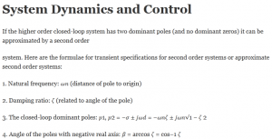
If the higher order closed-loop system has two dominant poles (and no dominant zeros) it can be approximated by a second order
system. Here are the formulae for transient specifications for second order systems or approximate second order systems:
1. Natural frequency: ?? (distance of pole to origin)
2. Damping ratio: ? (related to angle of the pole)
3. The closed-loop dominant poles: ?1, ?2 = −? ± ??? = −??? ± ???√1 − ? 2
4. Angle of the poles with negative real axis: ? = arccos ? = cos−1 ?
5. The damped frequency of oscillations is the imaginary part of the roots: ??
6. The exponential time constant is the reciprocal of the real part of the roots: ? = 1? =1???
7. Distance of the pole from origin is √?2 + ?? 2 = ?? = natural frequency.
8. Settling time: ?? = 4? =4???
9. Peak time: ?? = ???
10. Maximum overshoot: ?? = ?− ??√1− ?2 = ?−? cot ? = ?−? ???
11. To get percent overshoot multiply ?? with 100.
Similar characteristics in the frequency domain are:
1. Resonant frequency of the closed loop system: ?? = ??√1 − 2? 2
2. Resonant peak amplitude the closed loop system: ?? = 12?√1−?2
Note that there is no resonant frequency or peak when the damping ratio is greater than 1√2 = 0.707
3. Cutoff frequency the closed loop system: ?? = ??√1 − 2? 2 + √1 + (1 − 2?2)2 Cutoff frequency tells about the bandwidth and is related to speed of the closed loop system. Higher cut-off frequency → higher bandwidth → lower settling time, rise-time, peak time.
4. Damping ratio of the closed loop system ? is related to the phase margin of the open loop system:
? = tan−1 2√√4+ 1?4 −2(?? ???????) ≈ 100? (?? ???????)The approximate formula for phase margin, 100?, works only for phase margins up to about 60 degrees.
Errors specifications:
1. For a typical system with a plant G and controller K.The error is ?(?) = 11+?? ?The steady state error is ?(∞) = lim ?→0?(?)? = lim ?→0??1+??
2. Steady state error for a step input R(s) = 1/s is:?(∞) = lim ?→011 + ?? =11 + lim ?→0?? =11 + ?? ???? ?? ?? =11 + ??
3. Steady state error for a ramp input R(s) = 1/s2 is:?(∞) = lim ?→01?(1 + ??) =1lim ?→0??? =1??If GK has no integrator ?? is 0 (ramp error is infinite). If GK has 1 integrator ?? is finite, it is the x-intercept (frequency
intercept) of the asymptote line from the left half of the bode(GK). If GK has more integrators ?? is infinite.
4. To reduce the error due to reference command (and disturbance dy) of frequency ? by a factor of F: |?(??)| > ? + 1 .
5. To reduce the error due to a sinusoidal noise command of frequency ? by a factor of F: |?(??)| < 1
1+? .
1. Most of the specifications for the system of the unity
feedback architecture shown on the right are boiled down to
Bode/Nyquist/Nichols plots of the GK(s).
a. If there was a sensor block ?(?) in the feedback
path, whose Bode/Nyquist/Nichols plots will you plot to check stability of the closed loop system?
b. If there was a prefilter block ?(?) after the reference command, whose Bode/Nyquist/Nichols plots will you plot to
check stability of the closed loop system?
2. Here is a Bode plot of some open loop system GK, plot the Nichols plot by hand. Show the gain and phase margins in there.
Is the closed loop system stable?
3. Mark the following No-go regions in the Bode plot of GK in Q2:
a. If you want error due to reference R in the frequency range 0 to 1 rad/s to be <1% of the R amplitude.
b. If you want error due to noise N in the frequency range 10 to 100 rad/s to be <1% of the N amplitude.
c. If you want error due to disturbance dY in the frequency range 0 to 1 rad/s to be <1% of the dY amplitude.
d. If you want error due to disturbance dU in the frequency range 0 to 1 rad/s to be <1% of the dU amplitude.